 In a previous article, “Implementation of Circle Mobility Mdel for ns-3 and Visualizing it in 3D“, I showed the creation of a new mobility model class implementation for simulating circular mobility under ns-3.
Even though a 3D visualization or even 2D visualization is not at all needed while doing scholarly research work, while learning the fundamentals of a simulation, for better understanding, all of us just want to visualize the network that we are simulating. For that, we need a better visualization of the simulated network.
In addition to that, the pictorial and video outputs of the simulated network will be useful to make one understand our ideas during our project or research presentations.
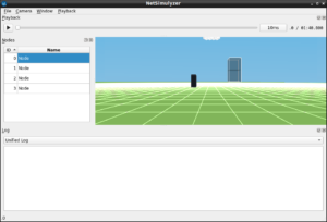
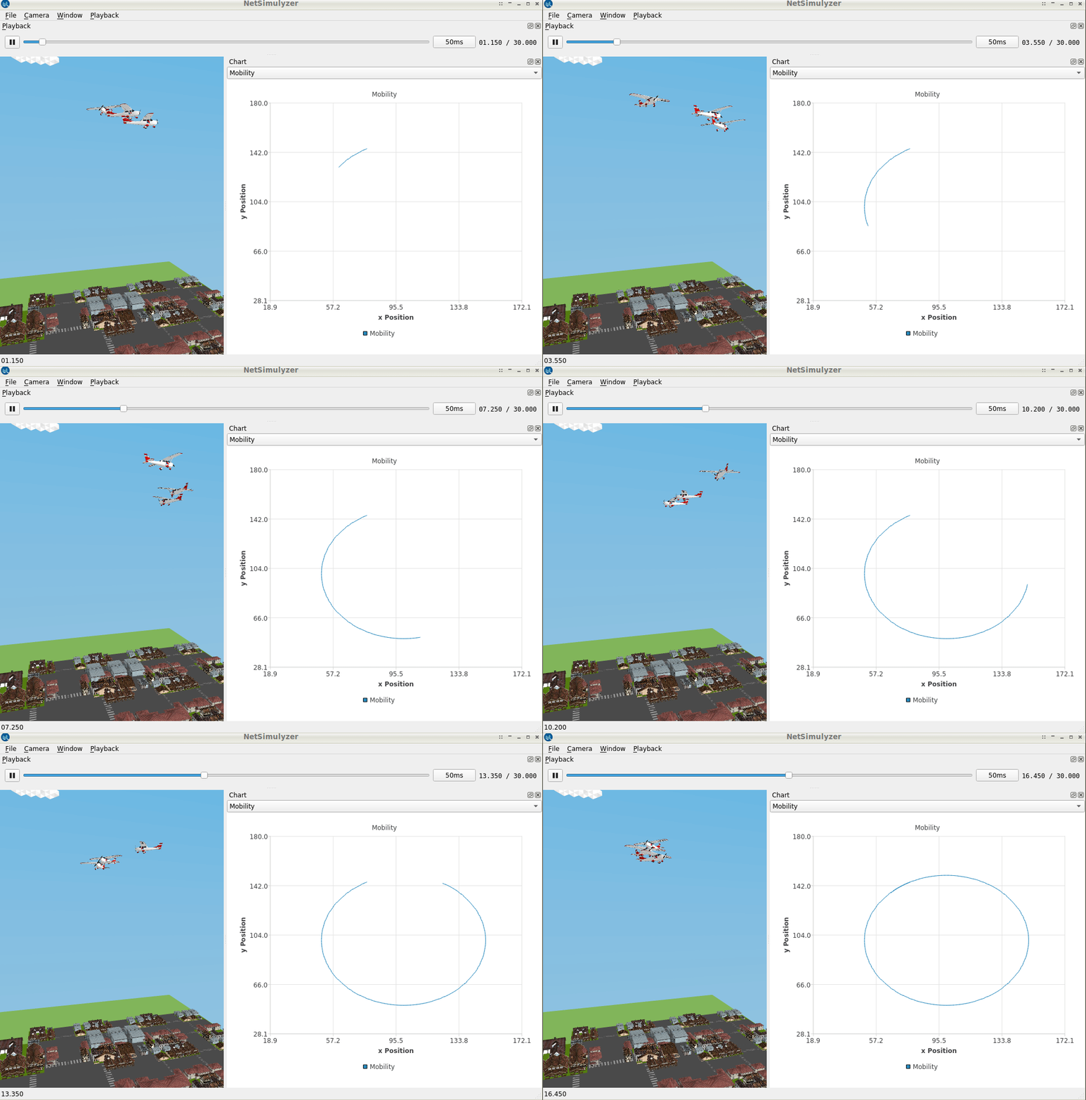
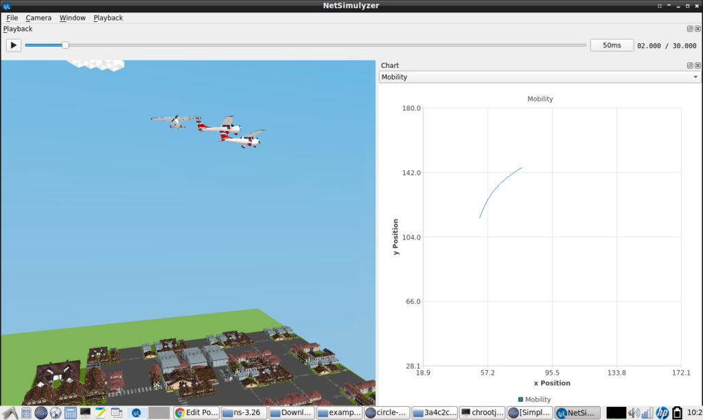
This article shows the way of visualizing the circular path using the graph feature available in NetSimulyzer. This example simulation is only for understanding the way to interact with the mobility model and the NetSimulyzer graph features.
Even though three FANET nodes are simulated in this example, to understand the basic idea, the graph is plotted for the path of the first node only.
Caution: This simulation only addresses the primitive problems in simulating and visualizing a 3D FANET Simulation and Mobility models. There are other aspects such as setting different routing protocols and different traffic types in such FANET scenario. They are not addressed in this article.
Further, there are some additional aspects needed to do a trace analysis on the simulated FANET scenario; that are also not discussed here. Further, for simulating realistic movements and orientation of 3d nodes, we have to do some modifications in the core Netsimulyzer. That is also not described here.
The Main Change in our Previous Circle Mobility Model.
For our design of “CircleMobilityModel”, earlier, I simply cloned one of the simplest mobility models called “ConstantPositionMobilityModel” and include the circular mobility functionality in it. The previously created CircleMobilityModel can make move in a circular path.
But it will not trigger the “CourseChange” event even though it is changing the course of the node at every instant of the movement in a circular path. I mean, while a node moves in a circular path, its position, as well as velocity, will change continuously overtime to maintain its movement in a circular path – but that version of the code will not trigger “CourseChange” event .
So, in this article, we will see some additions to our “CircleMobilityModel” to make the use of the “CourseChange” event in a ns-3 simulation. In addition to that, we will see the ways of visualizing the simulated circular path on a graph using the features available in NetSimulyzer.
The additons to our “CircleMobilityModel” Class of our “circle-mobility-model.h” file
The following are the aditional member functions and variables that are declared in CircleMobilityModel class of the header files circle-mobility-model.h.
void UpdateCourseChange (void);
Vector prev_vlelocity;
EventId m_event; //!< event ID of next scheduled event
The Important function added in our “circle-mobility-model.cc” file
One line was added in the function SetParameters of our previous CircleMobilityModel to enable triggering of the “CourseChange” event in a periodic manner.
void
CircleMobilityModel::SetParameters(const Vector &Origin, const double Radius, const double StartAngle, const double Speed)
{
DoSetPosition(Origin);
m_Origin=Origin;
m_Radius=Radius;
m_StartAngle=StartAngle;
m_Speed=Speed;
prev_vlelocity=DoGetVelocity();
m_event = Simulator::ScheduleNow (&CircleMobilityModel::UpdateCourseChange, this);
NotifyCourseChange ();
}
The New UpdateCourseChange Function
The following function will be called in regular intervals by triggering the “CoursChange” event accordingly in an ns-3 simulation.
void
CircleMobilityModel::UpdateCourseChange (void)
{
NotifyCourseChange ();
m_event = Simulator::Schedule (Seconds(0.1), &CircleMobilityModel::UpdateCourseChange,this);
}
The Components of the Simple 3D FANET ns-3 Simulation Script
The following code segment presents the important components of the ns-3 simulation script which is used to simulate and test our new circle mobility model. In this simulation, three aeroplane nodes will use the circle mobility model.
Include the header files Needed
The following lines include the necessary header files. The Netsimulyzer ns-3 module should be installed in the ns-3 directory tree.
#include “ns3/core-module.h”
#include “ns3/network-module.h”
#include “ns3/callback.h”
#include “ns3/mobility-module.h”
#include “ns3/netanim-module.h”
#include “ns3/netsimulyzer-module.h”
The following lines show the creation of nodes for this FANET network simulation.
NodeContainer CirclesUAV;
CirclesUAV.Create (3);
Simulate Circle Mobility in nodes
The following section of code will do the important part of adding mobility model in the nodes.
MobilityHelper CircleMobility;
MobilityHelper mobility;
CircleMobility.SetPositionAllocator (“ns3::RandomBoxPositionAllocator”,
“X”, StringValue (“ns3::UniformRandomVariable[Min=200.0|Max=250.0]”),
“Y”, StringValue (“ns3::UniformRandomVariable[Min=200.0|Max=250.0]”),
“Z”, StringValue (“ns3::UniformRandomVariable[Min=0.0|Max=250.0]”));
CircleMobility.SetMobilityModel (“ns3::CircleMobilityModel”);
CircleMobility.Install (CirclesUAV);
CirclesUAV.Get (0)->GetObject
CirclesUAV.Get (1)->GetObject
CirclesUAV.Get (2)->GetObject
Specify the output File and Set Different 3D models for the Simulated FANET nodes
Setting Parameters for the Graph
// Create XYSeries that will be used to display mobility (similar to a 2D plot)
posSeries1 = CreateObject
posSeries1->SetAttribute (“Name”, StringValue(“Circle Path of Airplane 1”));
posSeries1->SetAttribute (“LabelMode”, StringValue(“Hidden”));
posSeries1->SetAttribute (“Color”, netsimulyzer::BLUE_VALUE);
posSeries1->GetXAxis ()->SetAttribute (“Name”, StringValue(“x Position”));
posSeries1->GetYAxis ()->SetAttribute (“Name”, StringValue(“y Position”));
Scheduling the CourseChange Event
CirclesUAV.Get (0)->GetObject
Setting the New Call back function
CirclesUAV.Get (0)->GetObject
CourseChanged (Ptr
{
const auto position = model->GetPosition ();
posSeries1->Append ( position.x , position.y );
std::cout<<“CC “<
Add a Backbround Decoration
auto decoration1 = CreateObject
decoration1->SetAttribute (“Model”, StringValue(“HouseAndRoad.obj”));
decoration1->SetPosition ({0,0,0});
decoration1->SetAttribute (“Scale” , DoubleValue (2));
// decoration->SetAttribute (“Height”, OptionalValue
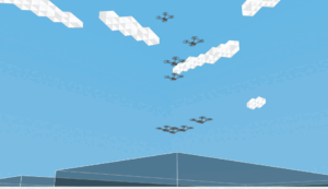
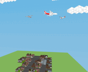
The 3D View of the simulated FANET in NetSimulyzer.
Configure standard NetAnim file and end the simulation
For comparison purposes, we create a NetAnim simulation file, which will only be capable of showing 2D of this 3D FANET scenario.
AnimationInterface anim (“SimpleNS3FANETCircleSpringMobility3D-withGraph.xml”);
Simulator::Stop (Seconds (200));
Simulator::Run ();
Simulator::Destroy ();
The 3D Circle Mobility Model Demo
The following video shows the 3D output of the FANET simulation with CircleMobilityModel.
Note: The visualization of Packet Transmission and wave Propagation on Medium are not yet implemented in NetSimulyzer. Further, the movement tracking using lines is also not yet implemented in NetSimulizer. So we can only see the movement of nodes. But we can add “log events” to understand the events of transmission and reception through some text messages that will be displayed in a separate text window of NetSimulyzer.

 Discuss Through WhatsApp